Seagate External Drive LEDs in Linux
Contents |
Note: If you simply want the software to control the LEDs, see seagate-leds.
Introduction
Recently, I purchased a Seagate GoFlex Desk USB 3.0 external hard drive (Model STAC1000101). (These seem to have been replaced with the Backup Plus Desktop). This drive is equipped with a pulsing (PWM) activity LED and 4 other LEDs that form a capacity gauge indicating the remaining disk space. I noticed these LEDs don’t function in Linux and there does not appear to be any Linux software to support them.
So naturally I felt an obligation to fill in this little feature gap. I’m not aiming for a full alternative to the Windows software, I just want to be able to control these LEDs in Linux.
There were two obvious ways to proceed:
- Analyze the USB traffic generated by the Windows software
- Debug the Windows software and find the LED control functions
I will start off with #1.
Analyzing USB traffic
There are a number of ways to capture the USB traffic. Here’s my plan:
- Run Windows in a VM
- Capture the traffic with usbmon
- Analyze the traffic with Wireshark
Windows software
There are a few different pieces of software available to work with these drives in Windows:
Seagate Drive Settings was a tad buggy so I avoided it. Seagate Dashboard is the software that comes bundled on the drive so I decided it was the best place to start.
Interesting note: The package GoFlex_BundledSW.zip contains two .svn directories that point to an internet-accessible SVN server at https://sjsvn.memeo.us:22223/ocsvn/dashboard and an author of jtran. Oops!
I installed it in a Windows 7 VirtualBox VM. When I connected my drive, all 5 of the LEDs turned on which is perfect. The only partition I had was an ext4 partition so I was glad to see Seagate Dashboard did not really mind too much.
After that, I located the option to control the LEDs:
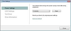
That will make it easier to trim down the USB traffic to only what I am interested in.
usbmon/Wireshark
usbmon is a linux module that enables the capture of I/O traces on the USB bus. I’ll use Wireshark as well because it has nice dissectors and a GUI. First, I loaded the usbmon module:
# modprobe usbmon
This creates a device for each USB bus: /dev/usbmon1, /dev/usbmon2, … (usbmon0 is “all buses”). Now I need to determine which bus the drive is on:
      lsusb
$ lsusb
Bus 001 Device 002: ID 0bc2:50a1 Seagate RSS LLC
...
The drive is on bus 1 (device 2). That means /dev/usbmon1 is the device I will use to capture traces. To avoid the need to run Wireshark as root, I modified the permissions of this device:
# chmod o=rw /dev/usbmon1
Note: Obviously this creates a bit of security issue until usbmon is unloaded.
The Capture
For my first capture I wanted to see the traffic generated when pressing “Turn Lights On”. The steps I took were:
- I made sure the LEDs were off
- I started a capture in Wireshark
- I pressed the “Turn Lights On” button
- I stopped the capture
I repeated this with the “Turn Lights Off” option. The resulting captures:
I’ll analyze turn_lights_on next.
Analysis
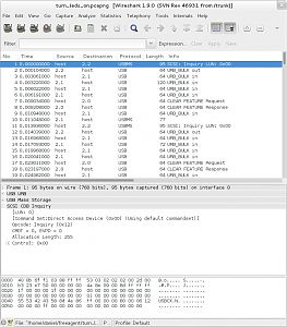
When I originally viewed the turn_lights_on capture in Wireshark, I found it to be a bit lacking. The dissectors were not giving much information.
A quick look through the data turned up the strings “USBS” and “USBC” which, thanks to Google, pointed me in the right direction. Apparently Wireshark did not identify the interface class as mass storage and thus failed to identify certain SCSI protocol elements. A quick patch yielded something slightly better:
The SCSI Inquiry pieces are generally a read operation used for obtaining serial numbers, etc. What I’m interested in are the SCSI commands.
SCSI Commands
Here’s the first SCSI command (0xFA), as printed in Wireshark:
      No.     Time           Source                Destination           Protocol Length Info
     71 0.098032000    host                  2.2                   USBMS    95     SCSI Command: 0xfa LUN:0x00

Frame 71: 95 bytes on wire (760 bits), 95 bytes captured (760 bits) on interface 0
USB URB
USB Mass Storage
    Signature: 0x43425355
    Tag: 0x864e8d58
    DataTransferLength: 4
    Flags: 0x80
    .... 0000 = LUN: 0x00
    ...0 1010 = CDB Length: 0x0a
SCSI CDB 0xfa
    [LUN: 0]
    [Command Set:Direct Access Device (0x00) (Using default commandset)]
    SPC-2 Opcode: Unknown (0xfa)
    Data (10 bytes)

0000  c0 03 0c ea 03 88 ff ff 53 03 02 02 02 00 2d 00   ........S.....-.
0010  b3 23 e7 50 00 00 00 00 3a 0d 0b 00 8d ff ff ff   .#.P....:.......
0020  1f 00 00 00 1f 00 00 00 00 00 00 00 00 00 00 00   ................
0030  00 00 00 00 00 00 00 00 01 00 00 00 00 00 00 00   ................
0040  55 53 42 43 58 8d 4e 86 04 00 00 00 80 00 0a fa   USBCX.N.........
0050  00 00 00 00 00 04 00 00 00 00 00 00 00 00 00      ...............
Wireshark is not as friendly as it could be here, it does not tell me whether this USBMS operation is IN or OUT. This can be determined by examining the Flags item under USB Mass Storage. 0x80 => IN. Reading through storage.h of the linux kernel source is helpful here as well.
This command is requesting 4 bytes from the drive (DataTransferLength).
The data is returned in #74:
      No.     Time           Source                Destination           Protocol Length Info
     74 0.101040000    2.1                   host                  USB      68     URB_BULK in

Frame 74: 68 bytes on wire (544 bits), 68 bytes captured (544 bits) on interface 0
USB URB
Leftover Capture Data: 01ff55aa
The interesting part is the “Leftover capture data”. These are the 4 bytes being received by the host (computer): 01 ff 55 aa.
Moving on to the next SCSI command (0xF9):
      No.     Time           Source                Destination           Protocol Length Info
    147 0.204948000    host                  2.2                   USBMS    95     SCSI Command: 0xf9 LUN:0x00

Frame 147: 95 bytes on wire (760 bits), 95 bytes captured (760 bits) on interface 0
USB URB
USB Mass Storage
    Signature: 0x43425355
    Tag: 0x864e8d58
    DataTransferLength: 4
    Flags: 0x00
    .... 0000 = LUN: 0x00
    ...0 1010 = CDB Length: 0x0a
SCSI CDB 0xf9
This command is sending 4 bytes to the drive. These bytes are in #149 and are: 02 ff 00 00. I found the next SCSI command to be 0xF7 which reads in these bytes: 04 01 00 00. The final command was 0xF8 which sends: 04 0f 00 00. These are all the important parts.
Capture Summary
Here is the sequence I observed:
- Command 0xFA: Read:
01 ff 55 aa - Command 0xF9: Write:
02 ff 00 00 - Command 0xF7: Read
04 01 00 00 - Command 0xF8: Write
04 0f 00 00
Based on the similarities, I made the following assumptions:
- Command 0xFA: Read X (last 2 bytes are always read as 55 aa)
- Command 0xF9: Write X (last 2 bytes ignored)
- Command 0xF7: Read Y (last 2 bytes ignored?)
- Command 0xF8: Write Y (last 2 bytes ignored?)
I don’t know what X and Y are but I know they probably control the LEDs. At this point I needed to experiment a bit to figure out what these commands really do.
Experiments
So I need to experiment with these SCSI commands. How can I send SCSI commands in Linux? An easy way is sg3_utils.
My device is /dev/sdc.
Note: In general, it’s better to use /dev/disk/by-, especially with removable drives
Here’s a quick summary of commands for experimentation:
| function | opcode | command |
|---|---|---|
| Read X | 0xFA | sg_raw -n -r 4 /dev/sdc fa 00 00 00 00 00 04 00 00 00 |
| Write X | 0xF9 | echo -e "\x02\xff\x00\x00" | sg_raw -n -s 4 /dev/sdc f9 00 00 00 00 00 04 00 00 00 |
| Read Y | 0xF7 | sg_raw -n -r 4 /dev/sdc f7 00 00 00 00 00 04 00 00 00 |
| Write Y | 0xF8 | echo -e "\x04\x0f\x00\x00" | sg_raw -n -s 4 /dev/sdc f8 00 00 00 00 00 04 00 00 00 |
I used these commands to verify that 0xFA/0xF9 read/write the same data and 0xF7/0xF8 read/write the same data. The last two bytes for both commands never seem to change, no matter what is written to them.
So in the end, I drew the following conclusions:
- Commands 0xFA/0xF9 control the activity LED. Only the first byte seems to really matter (this isn’t quite the case as I found out later).
- Commands 0xF7/0xF8 control the four status LEDs. Only the first two bytes are functional.
For the activity LED, the values I have discovered are:
| Data | Result |
|---|---|
| 01 | Turn all LEDs off |
| 02 | Turn on activity LED. Pulse on disk access, stay on solidly after. This also enables control of the status LEDs. |
For the status LEDs (0xF7/0xF8), the first two bytes seem to have the following meaning:
- First byte: Number of LEDs to enable (interpreted another way: number of bits of the second byte to actually pay attention to)
- Second byte: Bitmask of the state of the status LEDs (0 - off, 1 - on)
So, the following sequence of commands should turn all status LEDs of this drive (and similar drives) on:
      ###### Turn on activity LED, enable status LEDs ######

echo -e "\x02\xff\x00\x00" | sg_raw -n -s 4 /dev/sdc f9 00 00 00 00 00 04 00 00 00

###### Turn all status LEDs on ######
echo -e "\xff\xff\x00\x00" | sg_raw -n -s 4 /dev/sdc f8 00 00 00 00 00 04 00 00 00
Conclusion
This is about all the information that I can get from the usb traffic alone. To confirm my assumptions I’ll need to do a bit of debugging.
Debugging the Windows software
Now it’s time to start inspecting this Seagate Dashboard software to hopefully confirm my understanding of these SCSI commands.
What to debug?
The first issue I had to figure out was what process should I debug or what executable should I disassemble?
It stands to reason that sending raw SCSI commands to a drive is a restricted operation, not something a userland program can normally do.
This is, however, something a service can do.
Looking in services.msc I found “Seagate Dashboard Service” (C:\Program Files\Seagate\Seagate Dashboard\SeagateDashboardService.exe).
Debugging
Services are not launched in the normal way so it’s easiest to simply attach a debugger (with privileges) to the process. I launched a debugger as an administrator and attached to the running SeagateDashboardService.exe process. The first thing I noticed was a bunch of messages printed out like:
      I: 1/1/2014 1:35:22 AM (tid <no name>, 49) - RemoteServerImpl::DoRefreshCapacityLed() - Set new CapacityLedsOnCount=4
I: 1/1/2014 1:35:22 AM (tid <no name>, 50) - RemoteServerImpl::GetAllExternalDrives() - Returning all cached drives. count=1
I: 1/1/2014 1:35:22 AM (tid <no name>, 49) - RemoteServerImpl::SetSelectedDevice() - Set new device:GoFlex Desk - \\.\PHYSICALDRIVE1
So there is some debugging log that is being printed out which is nice.
Looking through the recognized functions I can see there is some debugging info present as some functions have names (such as stxdevif_?SendCommand@CsendToService@@QAEHXZ). I can use something like demangler to see what kind of signature these functions have without analyzing them a bunch.
There are a number of ways I can proceed from here:
- Search the process memory for the string LED or light
- Search for function names containing LED or light (since some debugging info is present)
- Set breakpoints on Windows API calls that can send SCSI commands to devices
- Set breakpoints on all recognized functions and see what breakpoints are hit when pressing the “Turn Lights On/Off” button
Since I don’t have a clue what Windows APIs can be used to send SCSI commands, I’m going for the last option. Specifically what I did was:
- Place a breakpoint on all recognized functions
- Run it and disable all breakpoints that are triggered
- Once it runs without triggering any breakpoints, hit the “Turn Lights On” button
- Step through functions until I see the lights actually come on
- Look at the last function executed since it actually turned the light/lights on
This led me to a function that was calling DeviceIoControl. Stepping over this function call shows that it is indeed sending SCSI commands to the drive.
I won’t go into details due to the effort it would take, but it’s pretty simple to figure things out from here.
Conclusion
At this point I have a pretty clear picture on how to control the LEDs of this drive. The final result is available on github: